-
Josh_S
- Registered User

- Posts: 498
- Joined: Fri Sep 11, 2009 3:34 am
- Real Name: Josh S
- YouTube Username: BLS
- Location: Oak Creek, WI
DC Siren Charging/Contactor Circuit - Opinions?
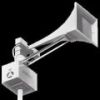
I’m trying to replicate a DC siren charging and contactor circuit. I’m fairly certain I came up with something that will function, but I’m hoping the experts might be able to chime in? Correct me if I am wrong with any of this. This will run a T-128. Basically I’m under the impression ASC separates the charging circuit from the run circuit via 4 relays controlled by the contactor circuit. When the contactor closes, the relays switch to a N/O position. As far as charging, I saw the 12V chargers are wired in series, therefore producing 12V, 24V, 36V, and 48V. Not sure if these are run of the mill chargers, or special ones. I know they just plug into a power strip in the control box so I’m assuming not the latter. ASC only specifies “Charger, 3A @ 12V, 2 Stage, Potted, Guest.” Threw in the fuses ASC specifies on the logic board diagram. Here’s what I have:
- Attachments
-
- 157DF58F-482C-4A63-ABA3-324E622DD3B3.jpeg (835.28 KiB) Viewed 2163 times
Proud owner of a 3T22A, a T-128DC, P-10, P-15, Model 5, T-135AC/DC, Alertronic AL-100, and a wide variety of various siren junk
-
Josh_S
- Registered User
- Posts: 498
- Joined: Fri Sep 11, 2009 3:34 am
- Real Name: Josh S
- YouTube Username: BLS
- Location: Oak Creek, WI
Re: DC Siren Charging/Contactor Circuit - Opinions?
And the chargers wired in series
- Attachments
-
- F022BC5F-58B1-497C-9A6E-2819F8684028.jpeg (744.43 KiB) Viewed 2162 times
Proud owner of a 3T22A, a T-128DC, P-10, P-15, Model 5, T-135AC/DC, Alertronic AL-100, and a wide variety of various siren junk
-
JasonC
- Administrator

- Posts: 3447
- Joined: Mon May 15, 2006 5:49 pm
- YouTube Username: Jsncrso
- Location: OBX, NC
Re: DC Siren Charging/Contactor Circuit - Opinions?
For charging, your best bet it to get a couple of marine battery chargers with multiple outputs. Just connect the leads to the individual batteries and you're done, no relays required. Here are a couple of examples. For 4x12v batteries, two of the two bank models would be best.
https://www.westmarine.com/buy/guest--c ... ecordNum=6
https://www.westmarine.com/buy/promarin ... cordNum=24
https://www.westmarine.com/buy/guest--c ... ecordNum=6
https://www.westmarine.com/buy/promarin ... cordNum=24
Return to “Main Outdoor Warning Sirens Board”
Who is online
Users browsing this forum: Ahrefs [Bot], Google [Bot], Semrush [Bot] and 18 guests