-
Jpressman8

- Registered User

- Posts: 1331
- Joined: Wed Nov 12, 2008 1:47 am
- Location: Cincinnati,Ohio (White Oak Green Township)
The best thing to do is get a hold of the AF timer manual and circuit blueprints (if you have not retained one yet) and study how it works and the fuctions of each circuit, relay and microswitch etc. Also post some pictures of the wiring in your timer so everyone else can look at it. Someone may be able to spot the problem right away.
five liter V8
-
kx250rider

- Supporter

- Posts: 1801
- Joined: Mon May 15, 2006 5:12 am
- Real Name: Charles Murray Chilton
- YouTube Username: kx250racer
- Location: Dallas, TX
- Contact: Facebook
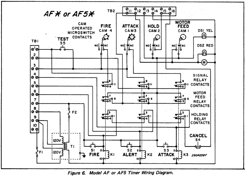
At a glance, I can't see which terminals the Cancel wires go to. For the missing jumpers, it's #15 & #16 on the small terminal strip, and #6 from the big terminal strip to #13 of the small one. Once you do that, the timer buttons should be reconnected. Yours is missing those jumpers because Derek says it had a radio controller attached. Since he says it was a custom radio, there might be something else that needs to be changed around. Not sure... He's a way more experienced tech on these than I am, so he can probably look at your pictures of the inside wiring and spot something, or I can try also. The diagram on the inside of the door is a little confusing too, at least from the way I see it.videogamer wrote:Ok is 11 and 12 susposed to be wired together? and is the brown wire (Guessing thats cancel) susposed to be going to terminal 12? and is 6 and 12 susposed to go to each other?
Don't feel embarrassed at all on this... My first timer had the missing jumpers, and I had no schematic diagram for it. It took me a long time to figure it out, and I was an ISO 9002 certified electronics technician when I worked for a defense subcontractor here in Los Angeles in the early 2000s.
Charles
Yes, that's a real 500-lb Federal SD-10 I'm holding (braggart!)


-
holler

- High Leg

- Posts: 5270
- Joined: Mon Jan 15, 2007 3:57 am
- Real Name: Jeb M
- YouTube Username: Blue10AEmia
- Location: Rhine, Georgia
- Contact: Website
Do you have a jumper between terminals 15 & 16?
If not put one in.
If not put one in.
Siren sales and service:
https://www.facebook.com/MccranieWarningSystems
https://www.facebook.com/MccranieWarningSystems
Speaking to Matt earlier, i got him to put a screwdriver across the terminals on the top of the motor feed switch very carefully. This set the timer off into a cycle. At that point i thought it was the switch gone but i may be wrong. All of the jumpers are installed on it, 15 to 16, 11 to 12, 13 to 7. He also said, before he did that, that the motor gets hot quite quickly. The 15 to 16 jumper would cause the behaviour of it, leading me to think that it could actually be the hold microswitch that's gone.
~Charlie J.
-
holler
- High Leg
- Posts: 5270
- Joined: Mon Jan 15, 2007 3:57 am
- Real Name: Jeb M
- YouTube Username: Blue10AEmia
- Location: Rhine, Georgia
- Contact: Website
Those little synchrous motors in these things heat up quickly. Every AR timer I've ever dealt with has a warm motor. Terminals 15 and 16 are for your cancel circuit. If you think a microswitch has gone bad check for continuity across the switch with your ohm meter. If it stays open all the time the switch is shot.
Don't buy them from federal either, they charge about $26 per switch, when I got mine from a canadian parts supplier for 6 a piece, and Eric Green probably has a good deal on some.
Don't buy them from federal either, they charge about $26 per switch, when I got mine from a canadian parts supplier for 6 a piece, and Eric Green probably has a good deal on some.
Siren sales and service:
https://www.facebook.com/MccranieWarningSystems
https://www.facebook.com/MccranieWarningSystems
OK it looks like CJ was right. The wire from 16 to the cancel terminal was not connected because I did not see it because it was under some tape hidden behind that tube with about 8 wires in it. I think when I was soldering I some how shorted out the cnacel button because it dose not work so now its just a trip to the flap-shack and it should be good to go! The only lights they have are in an odd shape but I will jsut get those for a temporary deal and then see if Eric has some spare parts.
videogamer
Matt Ullman
Matt Ullman
-
Andys Live WX

- Supporter
- Posts: 409
- Joined: Tue Aug 06, 2013 4:17 pm
- Real Name: Andy Thompson
- YouTube Username: andyt1424
- Location: Madelia, Minnesota
- Contact: Website Twitter YouTube
Re: AF timer help
I'm sorry I am bumping such an old topic, but where does the white wire go that comes from the secondary of the transformer?
Regards,
Andy Thompson
Electrician
http://www.somnwx,com
Owner of a 3T22A
Andy Thompson
Electrician
http://www.somnwx,com
Owner of a 3T22A
Return to “Main Outdoor Warning Sirens Board”
Who is online
Users browsing this forum: No registered users and 14 guests