Well, I think I'm going to use a DC motor as the rotator motor. (1/3hp, and most DC motors that size are 130VDC). Used ones seem to be cheap on eBay so that works.
Since the rotator and chopper motors will be off of the same circuit, I plan to wire the leads from the chopper transformer to a (x) position rotary switch to provide some sort of rotator speed control from the RCM. The output will then be fed into a full-wave bridge rectifier, which will turn the AC voltage into a rippled DC voltage (I may add a filter capacitor to filter the ripple some). The circuit will then feed into the DPDT toggle switch that will then reverse the + and - whenever the rotator makes one 360 degree revolution by manually hitting the switch.
I would like to still use my single phase rotator motor, but the motor would have to be brought to a complete stop and then reversed, something I don't know that would work with the setup I want because I foresee the motor getting hung up to much.
BTW, anyone know what size capacitor I'd have to use to use as a filter cap?
-
CDV777-1

- Registered User

- Posts: 1147
- Joined: Tue Jan 02, 2007 1:49 am
- Real Name: Eric
- YouTube Username: vanamonde2
- Location: Allen Tx
- Contact: Website
Jason. I think this would be the easiest way. The horn would only need to stop for a second to eliminate the high load when it reverses direction. As far as start up torque goes the gearing in the rotator gear reducer and pulleys hardly loads the motor at all. The only thing you would have to worry about is the load on the gear reducer gear and rotator driven gear. I think if you rig it for the horn to completely stop for a second then reverse direction it will be ok. To have it reverse direction with out a delay would probably strip the teeth off the gear. Maybe. The drive band might slip and allow the horn to keep moving. I think it would need a second or 2 delay to completely stop movement. 8 rpm would only put more load on it. That's way to fast.Now, I don't know to much about capacitor start motors like my rotator motor, but per Wikipedia: "The starting direction of rotation may be reversed simply by exchanging the connections of the startup winding relative to the running winding". So, with that in mind, I'm thinking about mounting a DPDT on-off-on switch that will be switched by the rotator pinion gear as it rotates to manually change the startup winding. Anybody have any thoughts/schematics/critiques at all on this? ANY thoughts or comments appreciated greatly!
-
JasonC

- Administrator

- Posts: 3447
- Joined: Mon May 15, 2006 5:49 pm
- YouTube Username: Jsncrso
- Location: OBX, NC
CDV777-1 wrote:Jason. I think this would be the easiest way. The horn would only need to stop for a second to eliminate the high load when it reverses direction. As far as start up torque goes the gearing in the rotator gear reducer and pulleys hardly loads the motor at all. The only thing you would have to worry about is the load on the gear reducer gear and rotator driven gear. I think if you rig it for the horn to completely stop for a second then reverse direction it will be ok. To have it reverse direction with out a delay would probably strip the teeth off the gear. Maybe. The drive band might slip and allow the horn to keep moving. I think it would need a second or 2 delay to completely stop movement. 8 rpm would only put more load on it. That's way to fast.Now, I don't know to much about capacitor start motors like my rotator motor, but per Wikipedia: "The starting direction of rotation may be reversed simply by exchanging the connections of the startup winding relative to the running winding". So, with that in mind, I'm thinking about mounting a DPDT on-off-on switch that will be switched by the rotator pinion gear as it rotates to manually change the startup winding. Anybody have any thoughts/schematics/critiques at all on this? ANY thoughts or comments appreciated greatly!
Ideally, this is what I would like. But there is an underlying problem. When the horn assembly completes it's revolution and switches the on-off-on DPDT switch to the off position, whats going to make it continue that much further to trigger the switch back to the opposite on setting? (an on-on switch wont work)I don't think there will be enough inertia to keep it going on that much further (even though its like a quarter inch). And if it does, I'm sure the motor would still be turning hwich would render the whole switching process useless (the motor has to be at a standstill to reverse) I just don't know, the rotator assembly is the only thing I've never really messed with so I don't know what it looks like in action up close on the inside. The torque issue shouldn't be a problem as by the time the motor has stopped, the horn will be stopped as well.
They basically allow current to be passed through a rotational device without getting wiring all caught up and twisted.Gil wrote:I know this is really off topic, but how do brush/collector ring systems work?
Jason, you could do it by getting the materials, but PVC pipe that will allow a solid rod to be inserted into it with about 2mm clearance, then another metal pipe over that.
Then use some silicone or some sort of industrial glue to hold it together.
Cheap and nasty, but still keep's the ol' beast on a 360? rotation.
-
JasonC
- Administrator
- Posts: 3447
- Joined: Mon May 15, 2006 5:49 pm
- YouTube Username: Jsncrso
- Location: OBX, NC
They maintain an electrical contact to something that is rotating or spinning that would otherwise pull wires apart. Basically, a carbon brush is physically drug around a copper ring to maintain this contact.Gil wrote:I know this is really off topic, but how do brush/collector ring systems work?
Apparently making one is much harder than I thought, well, without the proper tools at least. I dont have the tools to keep a good tolerance to actually put this siren back into service and trust it so thats why I want to oscillate it to keep it hardwired.
-
Gil

- Registered User
- Posts: 1920
- Joined: Mon May 15, 2006 11:55 am
- Real Name: Gil R
- YouTube Username: gilramirez12
- Location: IL
- Contact: Website YouTube
Oh ok. So let me get this straight. The rotator is connected to the chopper arse'y, and between that connection is the collector ring and the brush?JasonC wrote:They maintain an electrical contact to something that is rotating or spinning that would otherwise pull wires apart. Basically, a carbon brush is physically drug around a copper ring to maintain this contact.Gil wrote:I know this is really off topic, but how do brush/collector ring systems work?
Apparently making one is much harder than I thought, well, without the proper tools at least. I dont have the tools to keep a good tolerance to actually put this siren back into service and trust it so thats why I want to oscillate it to keep it hardwired.
-
JasonC
- Administrator
- Posts: 3447
- Joined: Mon May 15, 2006 5:49 pm
- YouTube Username: Jsncrso
- Location: OBX, NC
Yup.Gil wrote:Oh ok. So let me get this straight. The rotator is connected to the chopper arse'y, and between that connection is the collector ring and the brush?JasonC wrote:They maintain an electrical contact to something that is rotating or spinning that would otherwise pull wires apart. Basically, a carbon brush is physically drug around a copper ring to maintain this contact.Gil wrote:I know this is really off topic, but how do brush/collector ring systems work?
Apparently making one is much harder than I thought, well, without the proper tools at least. I dont have the tools to keep a good tolerance to actually put this siren back into service and trust it so thats why I want to oscillate it to keep it hardwired.
Justin, are you talking about a horizontal type brush ring plate (like the 1003 actually uses) or a vertical type with the rings on top of each other on the chopper tube (like this: http://www.semcomotion.com). I think I kinda see what you mean but how will you actually make the collector rings?
The thing is I'd love to make it a true rotating 360 degree siren, and I can do it, but I wouldn't trust the thing to be put back in actual service. Thats's what I'm aiming for.
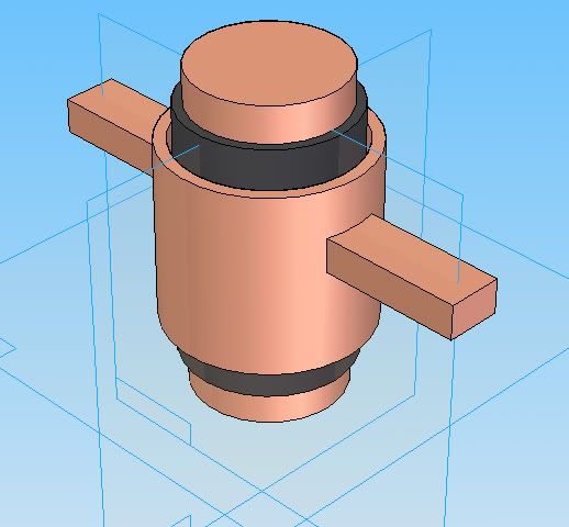
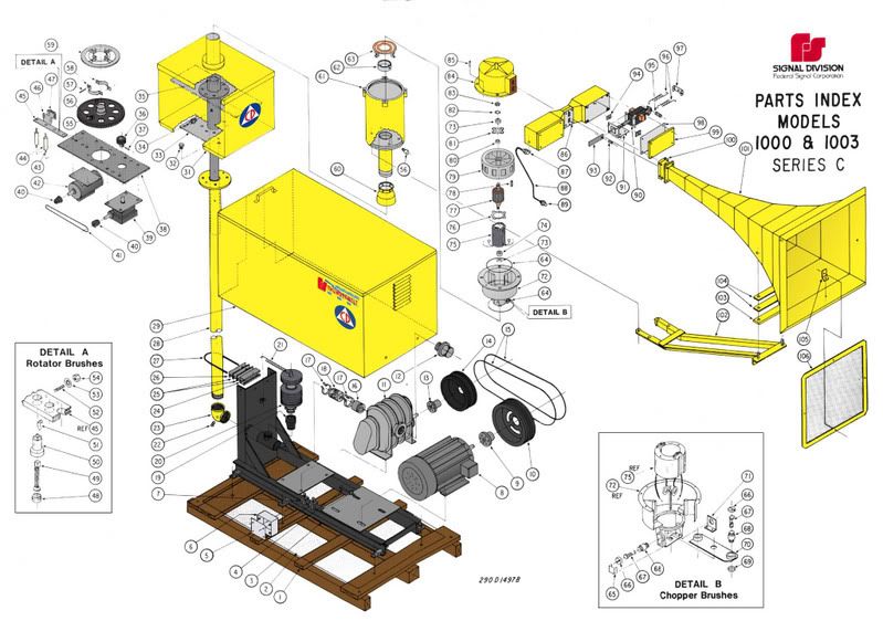
That's what I mean, but going off the parts list (below) you could almost use that as a replacement. The two copper coloured bits, are copper
I added the 'T' bars in there so you could fix the sliprings to something, but looking at the parts diagram; possibly not.
I'm convinced I'm missing something...
-
JasonC
- Administrator
- Posts: 3447
- Joined: Mon May 15, 2006 5:49 pm
- YouTube Username: Jsncrso
- Location: OBX, NC
Justin Savidge wrote:[img.]http://img.photobucket.com/albums/v349/ ... prings.jpg[/img]
That's what I mean, but going off the parts list (below) you could almost use that as a replacement. The two copper coloured bits, are copper, and the black is just some PVC piping as an insulator (garden variety
). To maintain contact, you could use a 'finger' of copper to maintain contact with both anode and cathode.
I added the 'T' bars in there so you could fix the sliprings to something, but looking at the parts diagram; possibly not.
[img.]http://img.photobucket.com/albums/v349/ ... tc2048.jpg[/img]
I'm convinced I'm missing something...
Wait.... is this a motor control for oscillating the T-bolt or are you going back to making a brush ring assembly fro full 360 degree rotation?
Return to “Main Outdoor Warning Sirens Board”
Who is online
Users browsing this forum: Ahrefs [Bot], Google [Bot] and 11 guests