Thunderbolt Restoration Part 6 - Solenoid timer, a side project
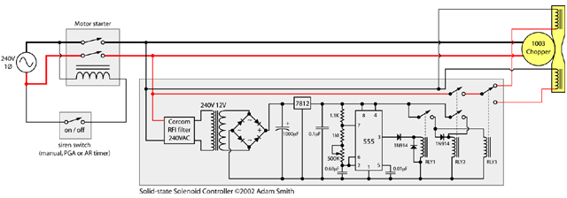
I don't have an AF timer, which is needed to do the high-low signal on the 1003. So, while paint was drying on the 1003, I decided to make an adapter of sorts for my 1003, to control the solenoids via a solid-state timer. The timer only needs to alternate the two solenoids every 0.5 seconds while the chopper is running, so I went with a 555-based 50% duty-cycle timer. Here is the schematic:

Click to enlarge this to a readable size
Circuit Description
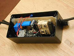
The circuit I built is the portion in the large grey box. The other wiring is for the power to the chopper motor, shown for context. I will explain it now, from left to right: First on the left is are the 240V power wires coming into the unit, which are coming from the motor starter that is controlling the 1003 chopper motor. Thus, my circuit has power to it whenever the chopper has power. When there is no power to the chopper motor, both solenoids are therefore open and the siren winds down in dual-tone mode.
The first element of the circuit is a commercially made Corcom RFI filter. I will only include this if RFI from the chopper motor causes problems for the 555 timer. Next in the circuit is a 240V-to-12V power transformer, bridge rectifier, storage cap and +12 volt regulator. These are the 12-volt power supply for my relays and the 555 timer chip. The 555 timer chip is configured as an astable multivibrator with 50% duty cycle of 0.5 seconds on and 0.5 seconds off alternately. For the large resistor determining the cycle period, I used a 1MEG resistor in series with a 500K trimpot. This provides some adjustablity in the timing to accomodate the tolerance of the capacitor (+/-10%) and the resistors, as well as some adjustability in general to the hi-lo durations.
The 555 output is connected to a high-impedance PCB-mounted miniature relay, RLY1. This relay closes whenever the 555 output is high. This relay's ultimate purpose is to switch relay 3 in sync with itself, relay 3 being the 10A contactor which does the actual switching of 240V power. I do not have the 555 switching this power relay directly because the coil on this relay is too low an impedance for the 555 output to drive. This leaves relay 2 (RLY2), can you guess what it's for?
Relay 2 is a HOLD relay that fixes a glitch in operation that would happen without it. When power is applied to my timer, it takes a finite amount of time for the 1000µF capacitor to charge up and for the 555's cycle to start. Without RLY2, power would be applied to the upper solenoid during this startup time. The 555 timer's cycle starts by outputting HIGH, which means the lower solenoid should be the first to activate. Thus, without relay 2, the upper solenoid would get a quick pulse of current that would sound like a mistake. So, the job of relay 2 is to keep the 240V power from reaching the solenoid switching relay (RLY3) before the 555 timer has started its cycle (before it goes HIGH for the first time). Once RLY2 has been activated, it latches itself closed by the 12V power through its lower set of contacts. The diode shown just to the left of RLY2 prevents RLY3 from being latched also.
Design Comments
Did I really need 3 relays to do a simple wig-wag timer? Probably not. This was a quick and dirty design and build on my part, and it probably could have been done in a less relay-intense way if I thought about it a bit more. RLY1 could be likely be replaced with a single transistor, possibly saving a couple bucks and compacting the design a bit. Does it matter? Not really, it works just fine!
Secondly, when I built this circuit, Radioshack.com was sold out of 240-to-12.6 volt transformers. I had to go with a 240-to-10 volt one, and Hammond 229A10. This is just barely OK. I was lucky in that the output of the 10V transformer is nearer to 16V with my light loading on it (out of spec?, who knows). I would have liked to use the 12.6V transformer though, to insure that the 7812 regulator chip was getting enough voltage headroom to work with. A true 10.0VAC transformer puts out voltage peaks of 14.14 volts. The bridge rectifier drops approx 1.4 volts (2 diodes in series on each half-wave) leaving 12.74 volts for the 7812. The 7812 requires approx 14.6V input to regulate properly, so I'm just lucky my transformer is lightly loaded enough that things still work OK.
Adam Smith ©2002
